In the following article I explain how to connect solenoid valves to the irrigation computer and what you need to bear in mind. At the end of the article I will discuss the special case of connecting a master valve.
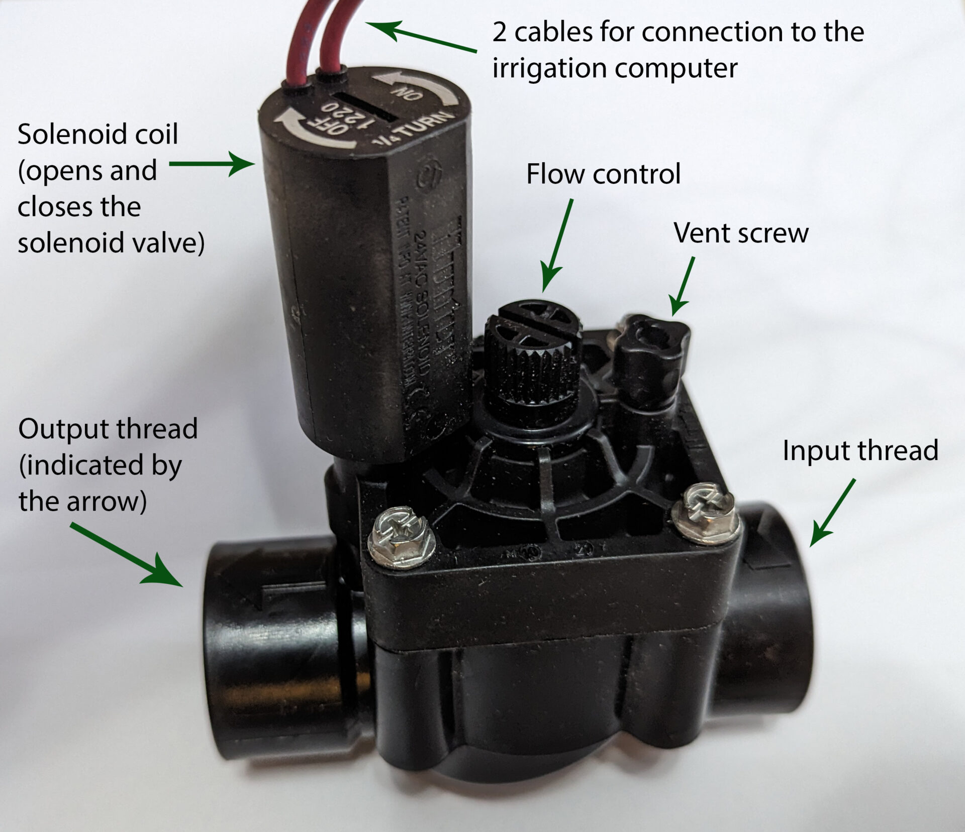
First of all, the typical structure of a solenoid valve used for garden irrigation is shown below, using the example of a Hunter PGV-101 valve:
The flow direction in which the valve is to be installed is indicated on the solenoid valve. Solenoid valves are available on the market with both internal and external thread connections. A flow control as in the example image is only included in some models. The models used in private irrigation generally have a 1 inch thread connection. The connection to the pipeline pipe is made with standard connectors using Teflon tape. The two outgoing cables are used to connect to the irrigation computer.
Where on the computer are the solenoid valves connected?
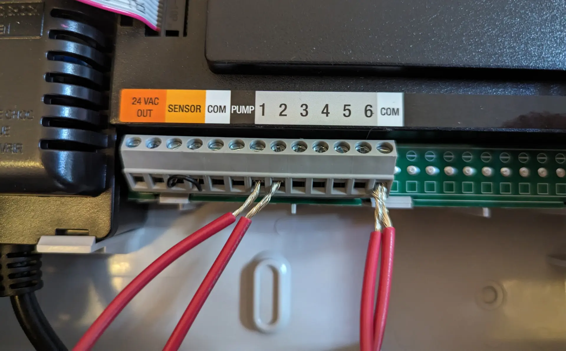
Irrigation computers typically have the following inputs and outputs, although these can be named slightly differently depending on the model:
Zone outputs numbered 1 to x – These are the outputs for switching the individual solenoid valves. Depending on the computer model, this has 4, 6, 8, 12 or even more zones.
COM or C – Stands for “common”. Used to connect the ground wires of the solenoid valves together.
SEN COM or SENSOR COM – Some watering computers have their own additional COM connections for connecting one or more sensors.
SENSOR, SEN or SN – For connecting sensors.
M, M/V, P or PUMP – For connecting a master valve or a pump start relay.
AC and GND – For connecting to the 230 volt power supply. Some watering computers already have a power cable with a Schuko plug pre-installed, others still need to be connected to the power supply; GND is intended for connecting the earthing cable.
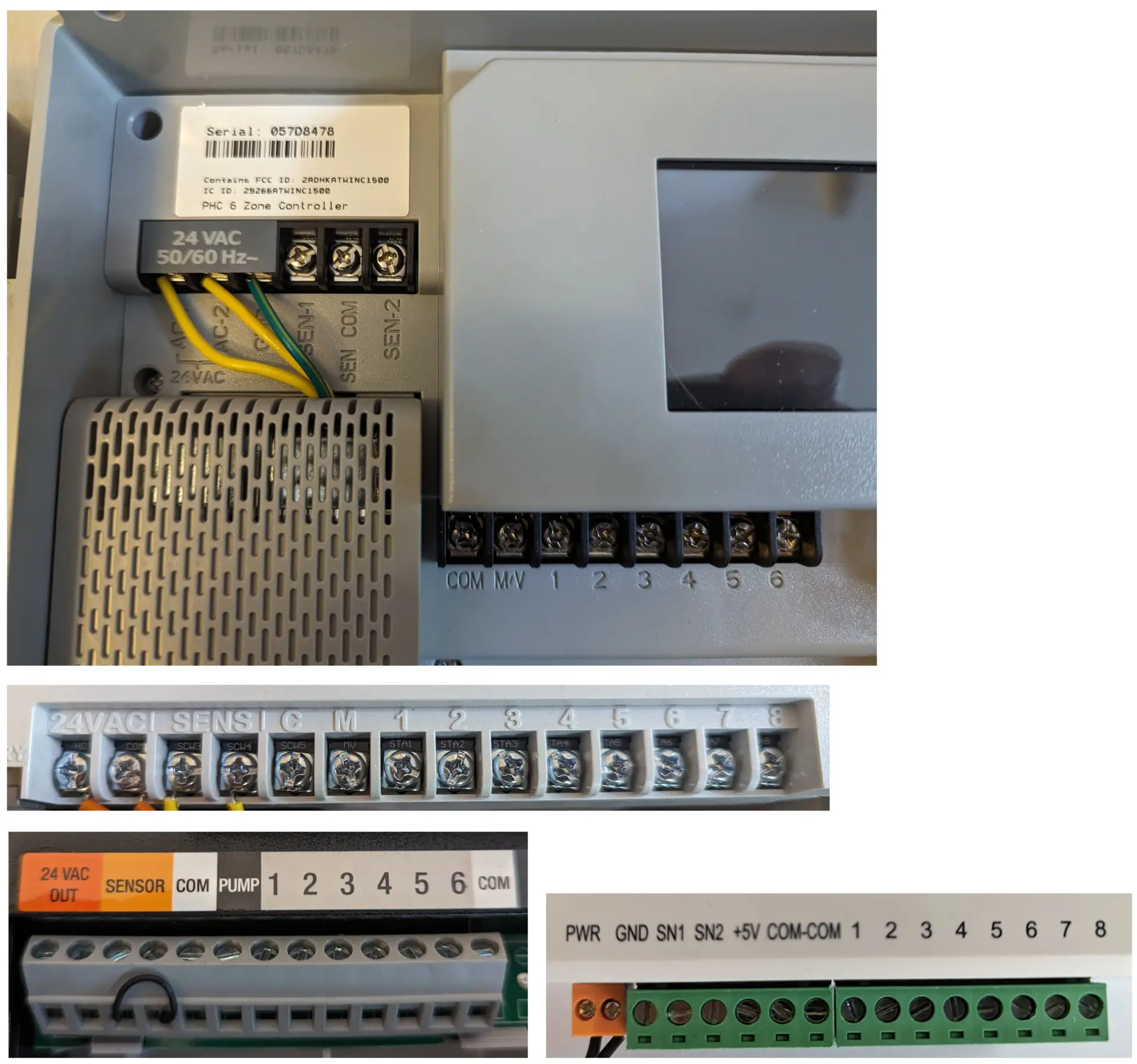
4 examples of typical connection relays based on the irrigation computers Hunter Pro-HC, Rain Bird ESP-TM2, Orbit B-hyve Smart Outdoor and Opensprinkler (from top left to bottom right)
How do you connect the solenoid valves to the watering computer?
The connection is made using the two wires mentioned above that lead away from the solenoid valve. One of the solenoid valve wires is used as ground, the other for control (referred to as an “active wire”). The ground wire is connected to the COM port of the watering computer, the one for control to one of the zone outputs. You can choose which of the two wires you use as ground and which as control.
Below is an example of connecting a single solenoid valve to the watering computer:
One wire of the solenoid valve leads to the COM port and one to a zone output (in this case the solenoid valve controls zone 1)
Each additional solenoid valve is connected in the following way: One cable is again led to the common COM connection, the other to a free zone output.
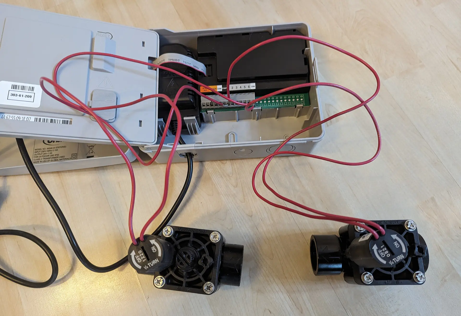
The connection when using two solenoid valves would therefore look like this:
The two wires of the first solenoid valve lead to zone 1 and the COM connection, those of the second solenoid valve lead to zone 2 and the COM connection. One wire is therefore led to the COM connection for each solenoid valve.
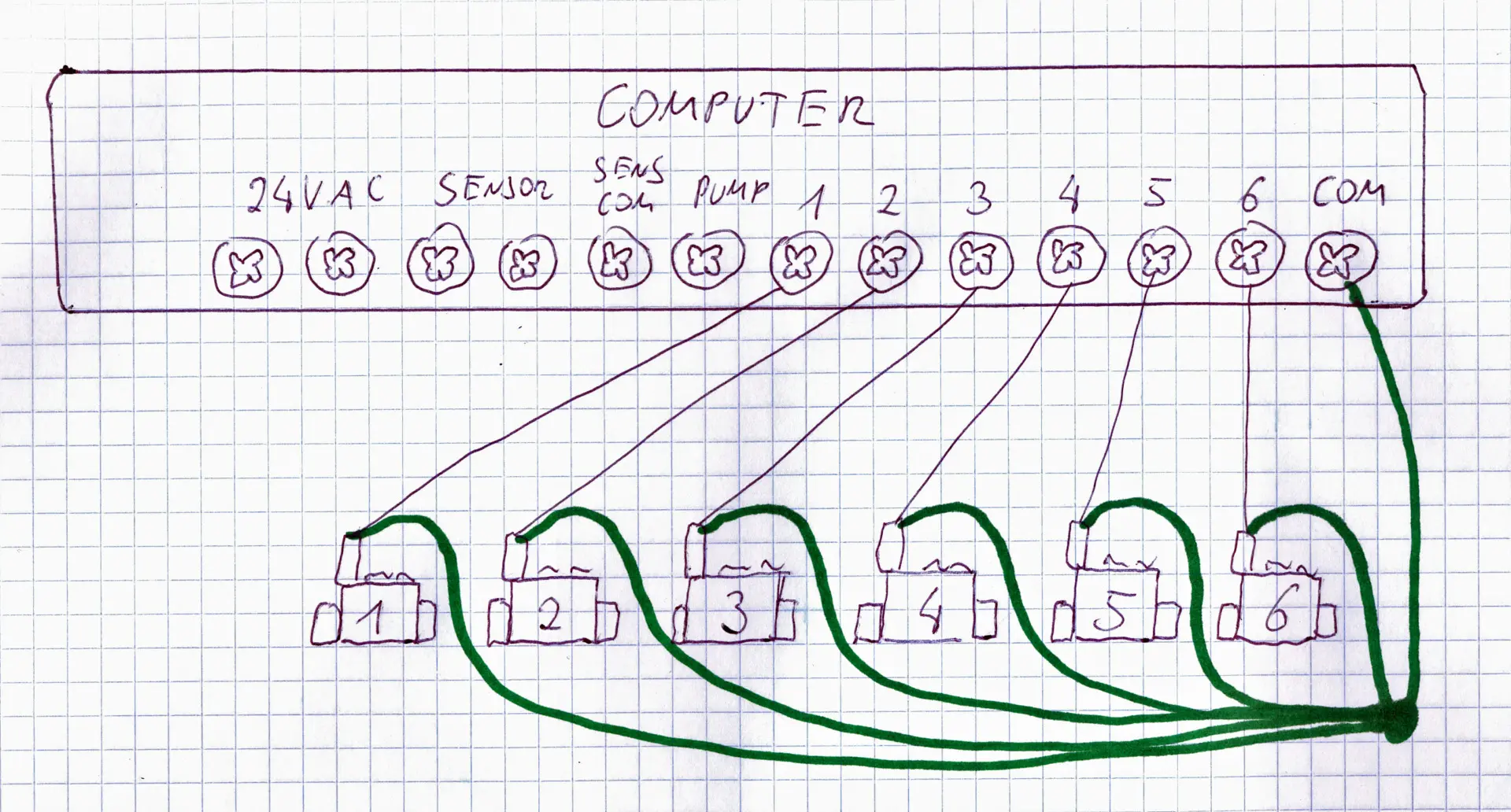
The theoretical principle is outlined again below. Here using 6 solenoid valves. The wires to the common COM connection are shown here in green:
Sketch for connecting 6 solenoid valves
How does the connection work in practice?
The basic principle is exactly as described above, but there are other things that need to be taken into account:
The irrigation computer is usually not located directly next to the solenoid valves and therefore the two wires leading from the solenoid valve are usually too short to connect the solenoid valves directly to the irrigation computer. An extension is therefore required.
In addition, the connections in the irrigation computer are not large enough to accommodate the wires of more than two or a maximum of three solenoid valves in the COM connection.
These are therefore brought together beforehand, outside the irrigation computer, and at the end only one common cable harness is led to the COM connection.
As the irrigation valves are usually located outdoors, the connections must be waterproof.
Control cable
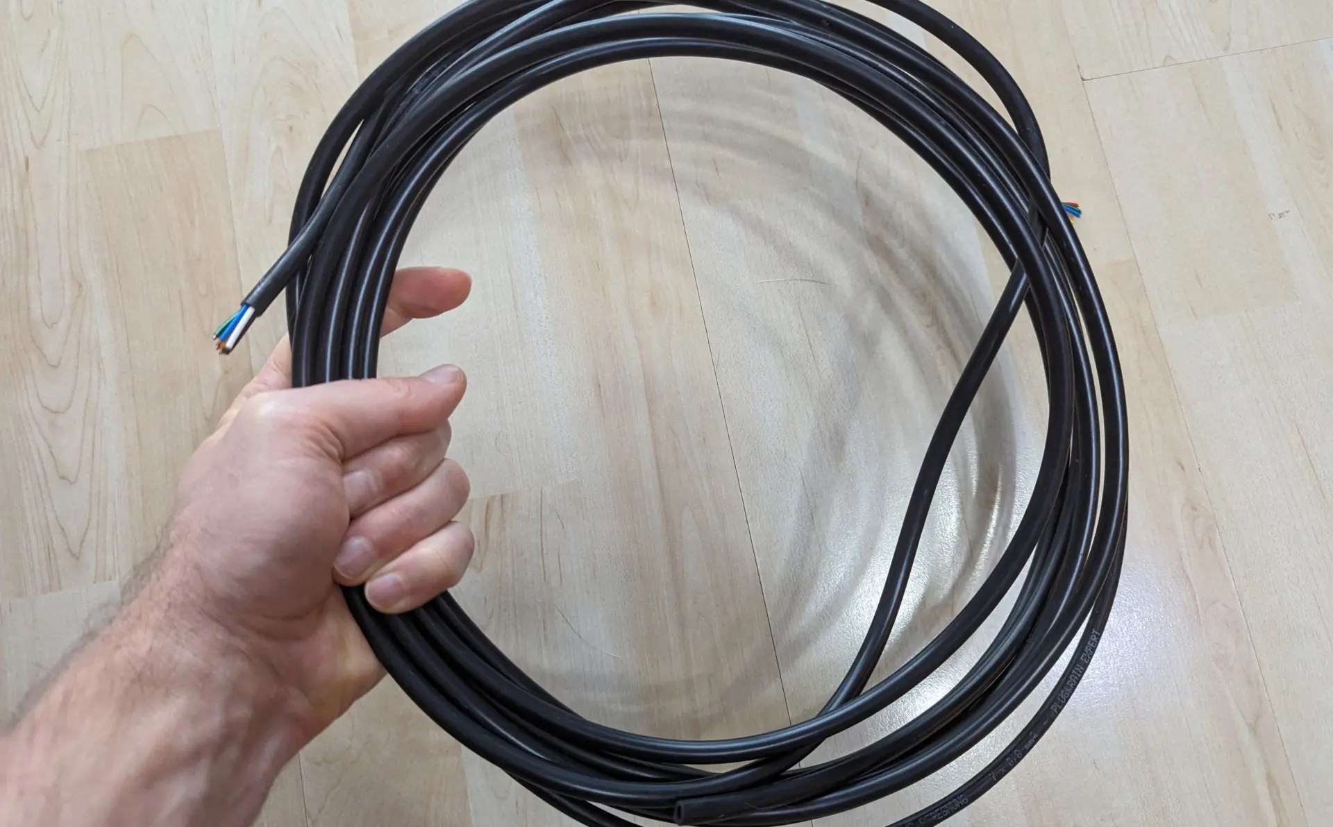
Solenoid valves are connected to the irrigation computer using a so-called control cable. This is a multi-core cable for low-voltage applications that has a significantly smaller cross-section than a power cable. Such control cables with a large number of wires are offered specifically by suppliers in the irrigation sector, among others.
Control cables are sold from the roll in pieces of several meters
Depending on how many solenoid valves you want to switch, you need a cable with the number of solenoid valves + 1 core. So if you want to switch 6 solenoid valves, for example, you need a 7-core cable, and if you want to switch 12 solenoid valves, you need a 13-core cable. I was able to find control cables with a maximum of 13 cores on the market, so for very large solutions you have to work with several control cables. Since the control cable is usually laid underground, it should be designed as an underground cable with a thick sheath.
Tip: To be on the safe side, it is advisable to plan 1 or 2 spare cores for possible future extensions. This saves you having to dig up again and pull a new cable if the worst comes to the worst. Since the cable can expand or contract slightly depending on the weather and in order to be prepared for any future adjustments, it is best to plan a small reserve in the cable length that is left at the valves after installation (approx. 3 cable loops).
The control cable is usually laid in the excavated trench along the pipeline main line (“mainline”) to the solenoid valves. It does not matter whether the solenoid valves are mounted in a valve box or on a hanging device for wall mounting, the connection to the control cable always works in the same way.
Waterproof connection
To protect the system from corrosion and short circuits and to increase its service life, the connections should be waterproof. Waterproof cable sleeves are recommended for this, as they provide good protection and are very easy to use.
If you are specifically looking for offers for such waterproof sleeves, I have put together the products I know of below:
Orbit 57002
Scotchlok 3M 314
3M DBR/Y
3M DBO/B
Hunter WC100
Rain Bird WC100
Practical example – This is how the connection is made
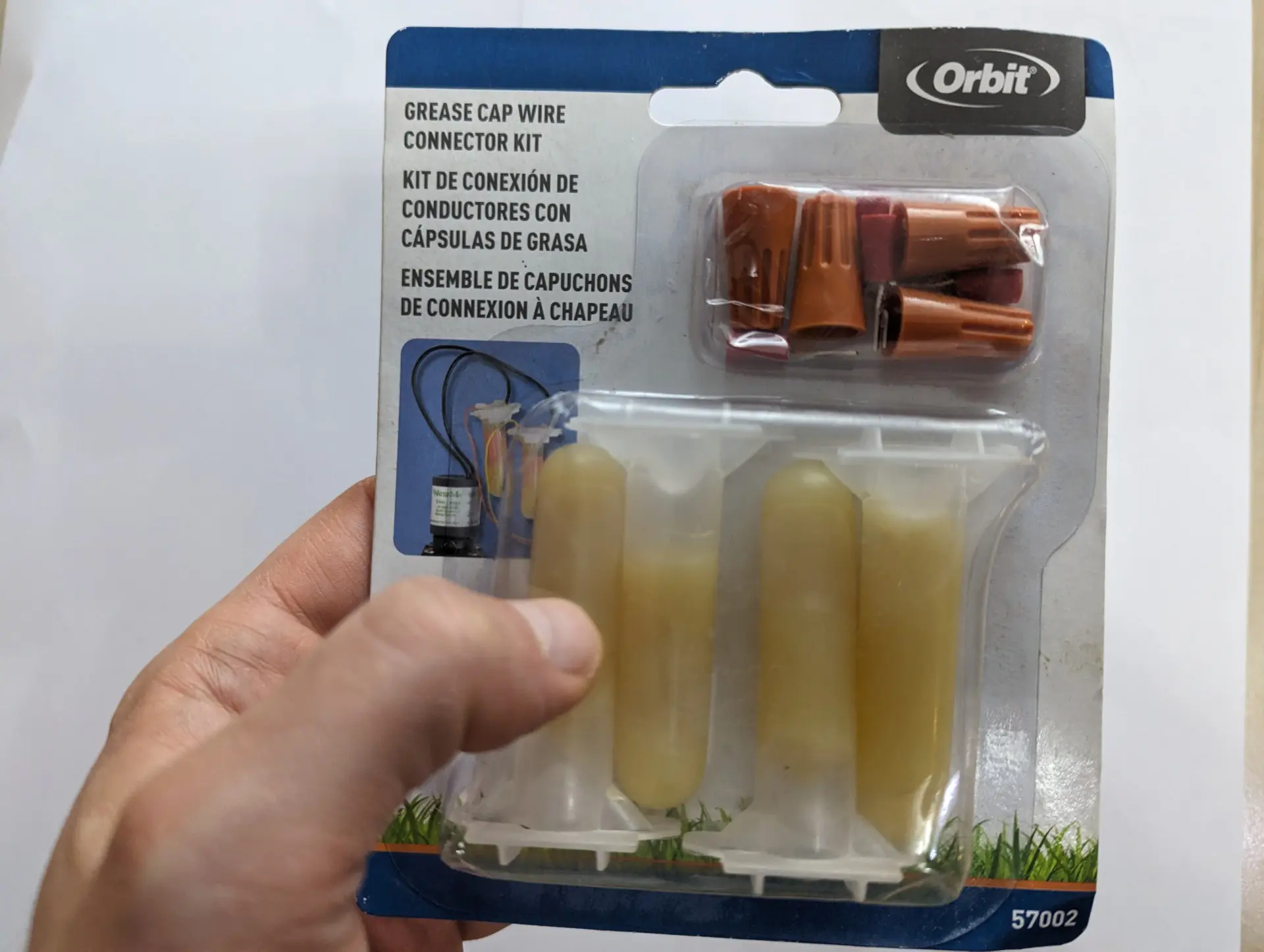
I will show this using the gel-filled sleeves from Orbit (Orbit 57002):
A pack of Orbit 57002 contains 4 grease caps, 4 wire nuts and 4 small fork connectors (not visible in the picture as they are hidden behind the wire nuts). These are not required for the connection.
Connect wires using wire nuts
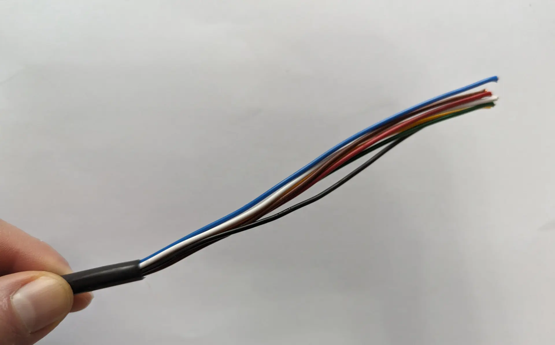
Step 1 – Carefully cut into the control cable sheath and pull it back a little to get to the individual wires:
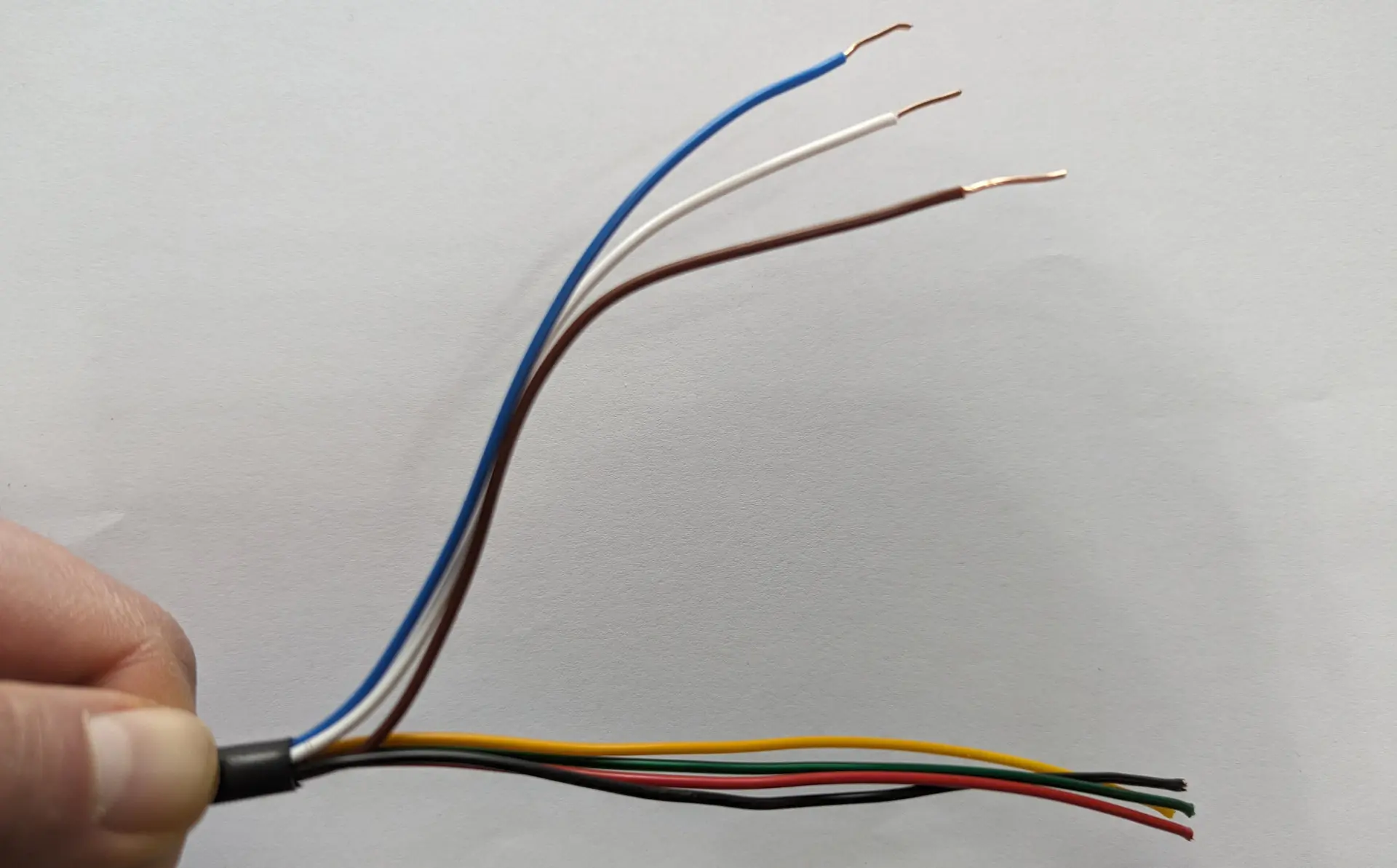
Step 2 – Strip the required wires (number of solenoid valves + 1)
I’m showing this here for connecting two solenoid valves. I use the white wire for ground, the colors for controlling the two solenoid valves can be chosen freely, in my case it is blue and brown. The other reserve wires remain insulated:
The wires leading from the solenoid valve are usually already stripped; otherwise, they would also need to be stripped in the same way.
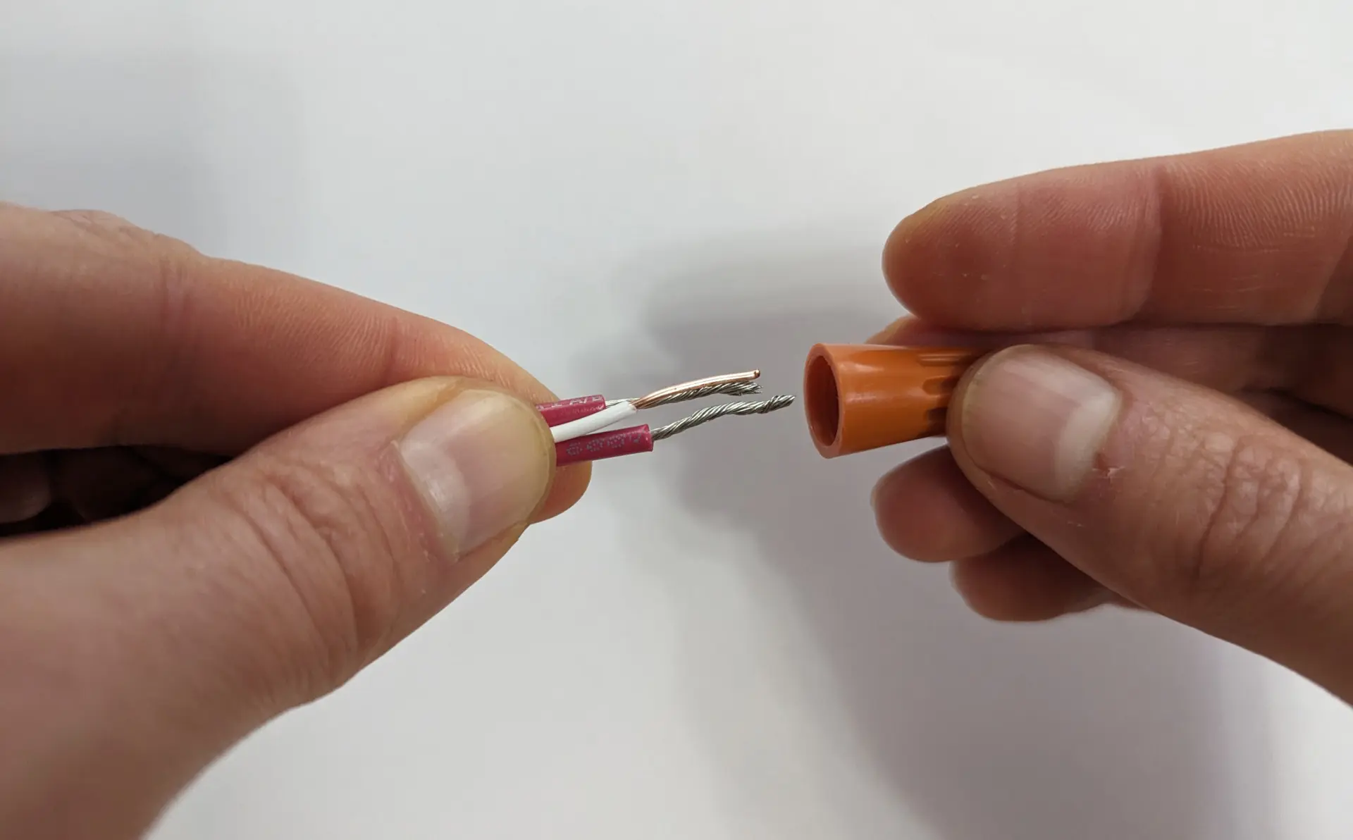
Step 3 – Creating the Ground Wire
In this step, connect one wire from each solenoid valve to the white wire of the control cable. To do this, the wires to be connected are placed flush with each other and inserted into the wire nut. In my example, there are two red solenoid valve wires that are connected to the white wire; in practice, depending on the size of the irrigation solution, there may be multiple solenoid valve wires. For larger solutions, ensure that the wire nut is sufficiently large!
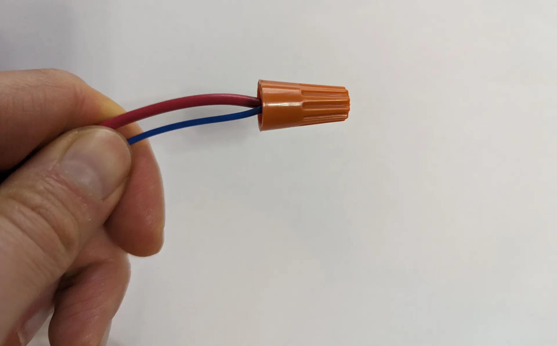
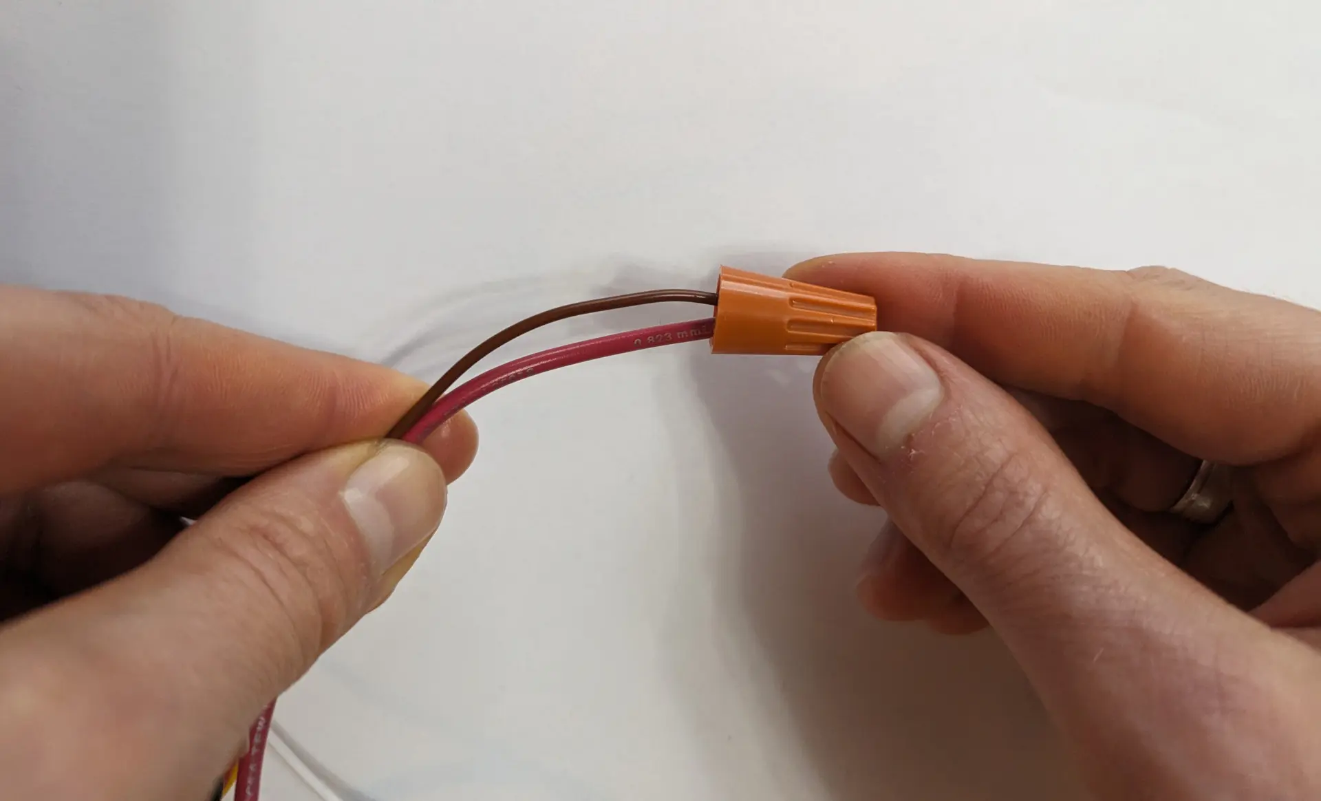
The wire nut is then turned clockwise over the wires, tightly twisting the wires together to create a stable connection:
Step 4 – Extending the Control Wires
Now, the second wire of the first solenoid valve, which is intended for control, is connected to one of the remaining wires of the control cable (in my case, I use the blue one) by twisting them together in a wire nut in the same way as described above:
Then the same happens with the second wire of the second solenoid valve, which in my case is connected to the brown wire of the control cable:
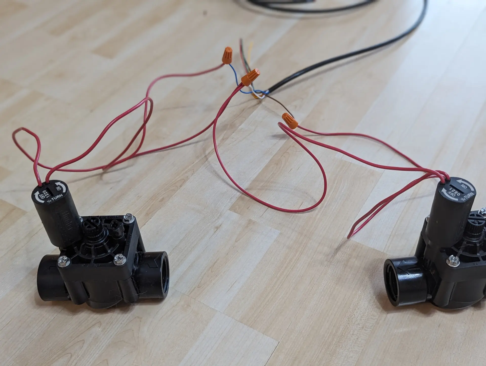
Now all four wires of the two solenoid valves are correctly connected to the ground wire of the control cable and the two wires of the control cable intended for control. In my example environment, this looks like this:
Before waterproofing the connections using the gel-filled cylinders in the next step, I recommend first conducting a short dry run test to ensure that the connections are correct and that the solenoid valves are switched correctly. Because once the wire nuts are sunk into the grease caps, it becomes a big mess to correct mistakes.
Dry-test solenoid valve circuits
To do this, the sheathing on the other end of the control cable is also removed a bit and the used wires are stripped.
Important: Disconnect the watering computer from the power supply before connecting the wires!
Now connect the wires to the watering computer: the two wires intended for control to the zone outputs and the white ground wire to the COM port. Unused wires are also not connected to the watering computer!
Now turn the water computer back on and test the wired zones one by one. In my case, these are zones 1 and 2. When the zone starts, you should hear a quiet click when the solenoid valve switches!
Great, the circuit is working! Before the next step, unplug the irrigation computer again!
Waterproof the connections
Step 1 – Open the grease caps and insert the wire nuts into the grease caps:
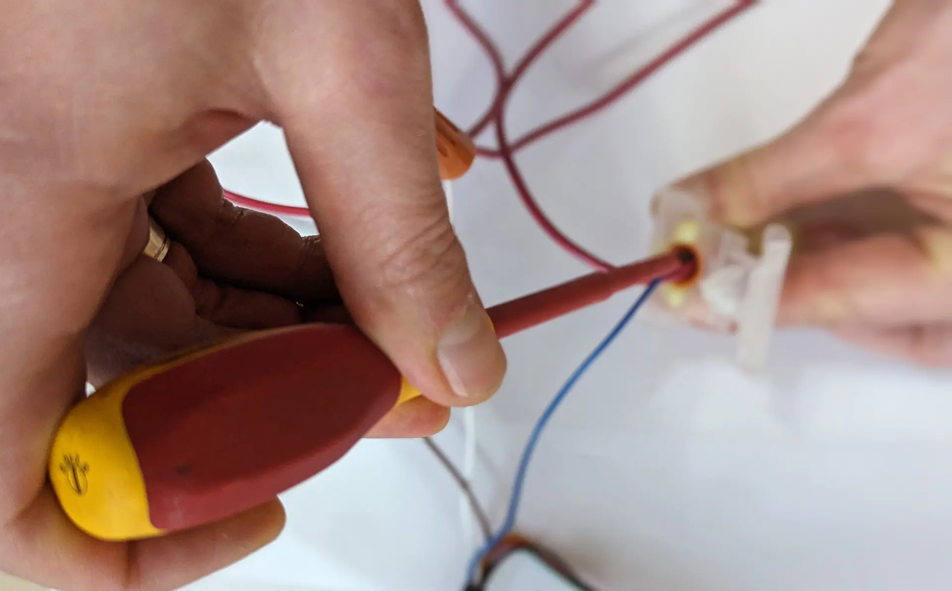
Step 2 – Push all the way to the end!
The wire nuts should be pushed all the way to the end of the grease caps for optimal protection from moisture. It’s best to use a long, narrow object, such as a screwdriver, to help with this. If you get some of the gel on your fingers, it’s difficult to remove even with soap, just like silicone. A wet kitchen wipe or baby wipe will help here; you can easily wipe it off with it!
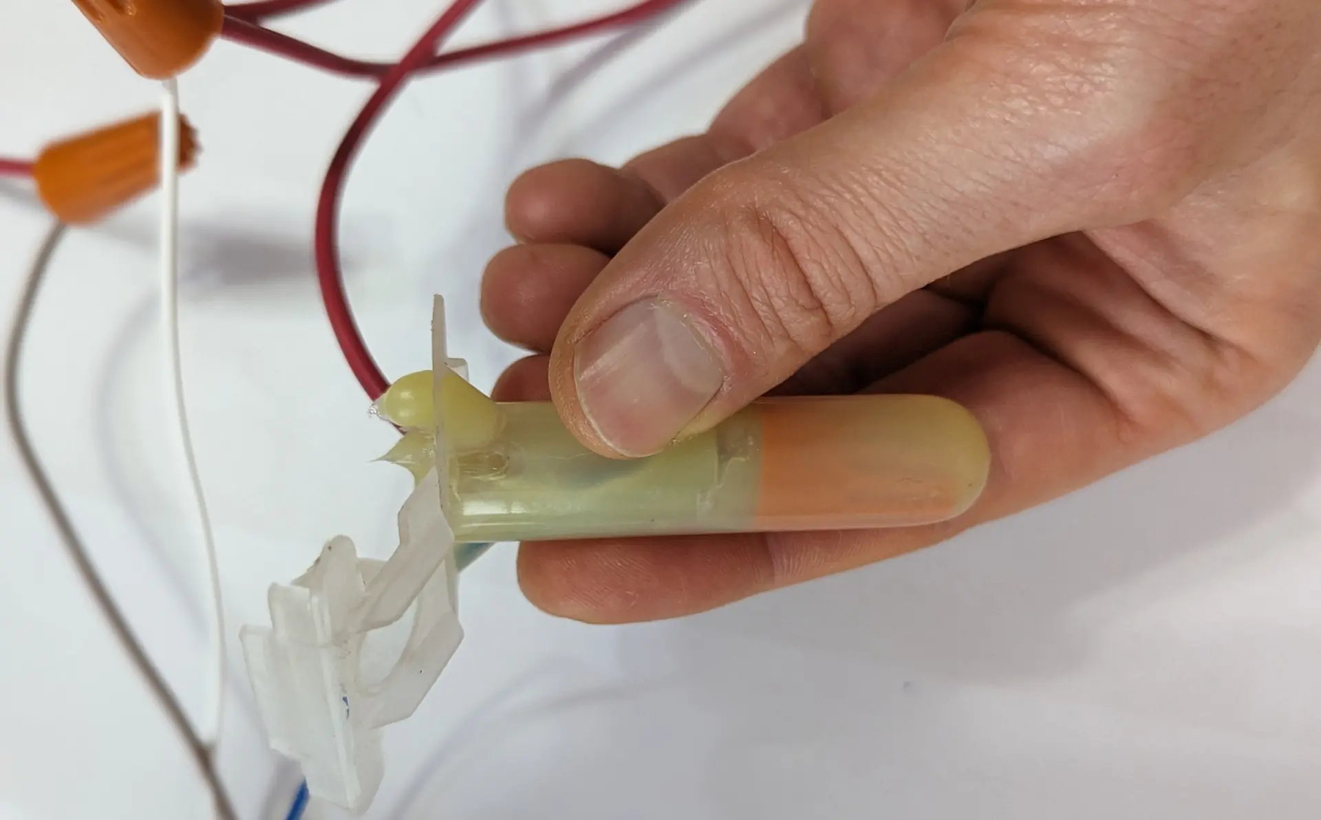
It should then look like this:
Step 3 – Close the grease cap.
To do this, place the two wires on the left and right into the designated channel at the entrance of the grease cap and press the cover closed:
Finally, wipe away any excess gel. This is what my finished, waterproof joint looks like:
And here in the overall view the connection between computer and solenoid valves:
In actual use in a solenoid valve box, it is best practice to place the pre-installed gel sleeves not at the bottom of the box, but rather near the top of the solenoid valves, along with the spare cable.
Connecting a Master Valve
A special case is the additional connection of a master valve. This is used to secure an irrigation system by placing it in front of the zone valves and opening and closing them simultaneously. If one of the zone valves fails to close properly, the master valve prevents the irrigation system from continuing uncontrolled. The same type of valve is used as a master valve as is used as a zone valve; it is called a master valve solely because of its intended use.
In the pipeline, the master valve must be installed upstream of the zone valves. When using a solenoid valve box, it is installed upstream of the valves in the box, so the water must first pass through the master valve before reaching the zone valves.
Connecting to an Irrigation Computer
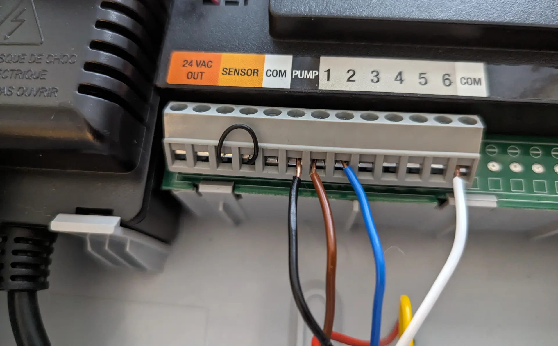
To use a master valve, you need an irrigation computer that supports it. This is usually the case with brand-name products. These either have a dedicated master valve connection (labeled M, M/V, P, or PUMP), or you can define any zone output as a master valve output in the computer’s software. In my example, an additional master valve would be connected as shown in the illustration. It is best practice to use the black wire of the control cable to connect the master valve.
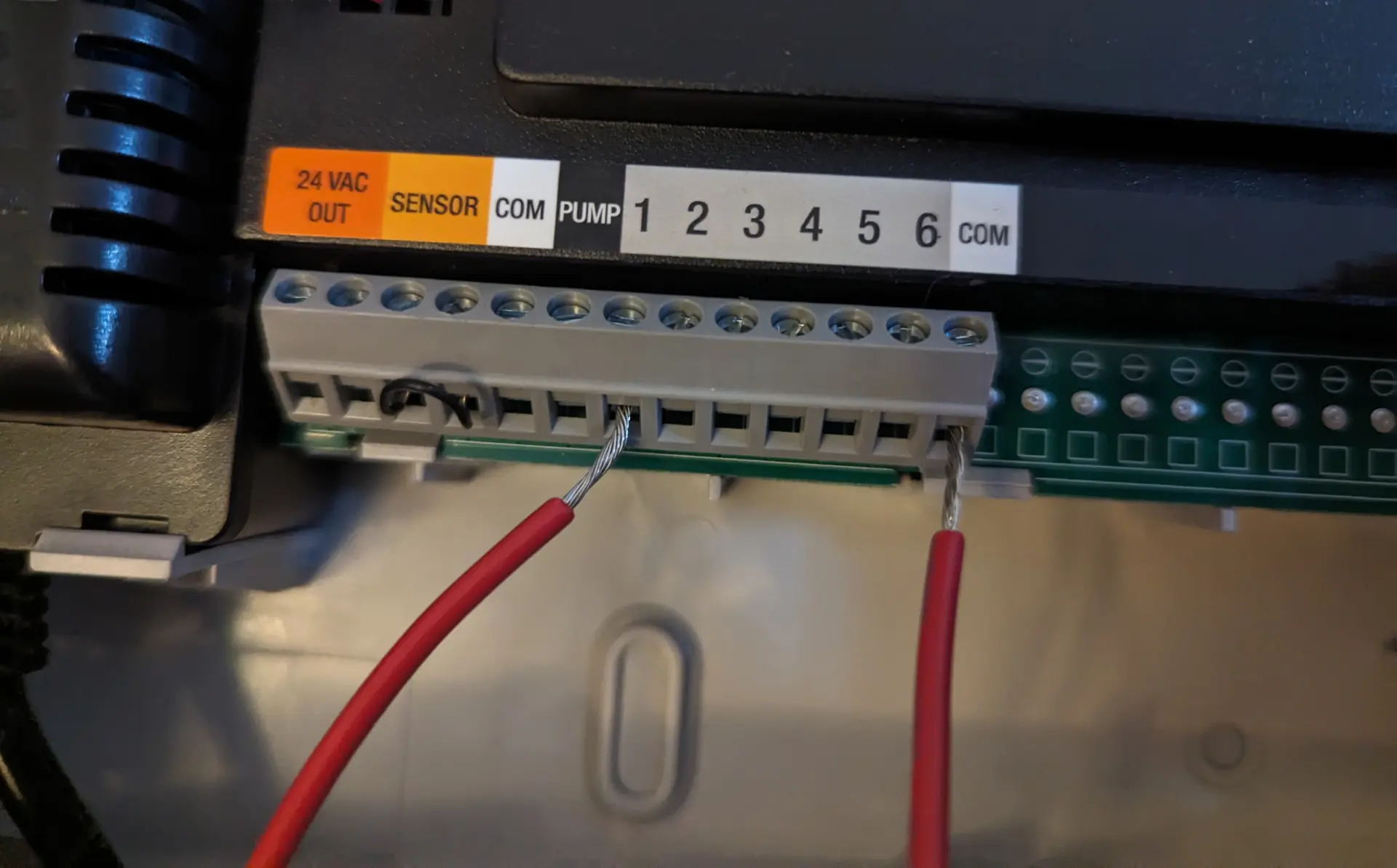
In the Orbit Computer used for illustration, the master valve is connected to the PUMP input
Connecting to the Control Cable
Connecting the additional master valve to the control cable works exactly the same as described above for the two solenoid valves: One wire of the solenoid valve is integrated into the ground wire, so that in my example, the wires of three solenoid valves instead of the previous two are bundled in the wire nut and feed the white wire. The second wire of the solenoid valve is connected with an additional wire nut to the black wire of the control cable, which leads to the master valve connection of the irrigation computer.
Activation on the Computer
In order for the computer to consider the master valve during irrigation runs, you must finally specify in the software that a master valve is being used. From now on, the software will always open the master valve as soon as a zone valve is opened and close it as soon as the zone valve is closed again. In better irrigation computers, it is also possible to define a specific time period, usually a few seconds, in which the master valve opens earlier or later than the zone valves. This can be useful in some situations to ensure appropriate pressure build-up.
I am an enthusiastic do-it-yourselfer and have been running this blog on the subject of garden irrigation for more than 6 years now. In over 150 specialist articles, I share my own experiences and know-how from years of research and numerous product tests. -> More about me